

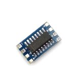
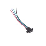
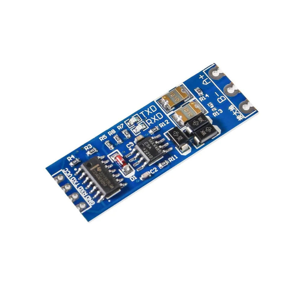
RS485 to TTL Converter Module Serial Port UART Hardware Automatic Flow Control Module
₹39.00 (inc. GST)
- No additional GPIO required for DE/RE control.
- Simplified UART programming.
- Easier integration with Arduino and ESP32.
- Convenient for Modbus RTU communication.
In stock
You’re now subscribed to price tracking for this product. We’ll notify you if the price drops.
MAX485 RS485 to TTL Converter Module – Automatic Flow Control Serial Communication Adapter
The MAX485 RS485 to TTL Converter Module is a compact serial communication interface designed to convert TTL UART signals into RS485 differential signals and vice versa. It enables reliable communication between microcontrollers, embedded systems and RS485-compatible industrial devices over long distances.
Based on the MAX485 RS485 transceiver IC, this module supports both 3.3V and 5V power supplies and TTL logic levels, making it suitable for Arduino, ESP32 and other microcontroller-based projects.
One of its key advantages is automatic transmit and receive direction control, eliminating the need for an additional GPIO pin to manually switch between RS485 transmission and reception. This simplifies hardware connections and makes serial communication easier to implement.
The module supports multi-device communication with up to 128 nodes on a single RS485 bus, subject to bus loading, cable and network conditions. It supports communication distances of approximately 800 metres under suitable conditions, making it useful for industrial automation, remote monitoring, sensor networks and distributed control systems.
Featuring onboard TXD and RXD indicator LEDs, a 120Ω termination resistor, standard 2.54mm pin spacing and a compact 0.8mm PCB design, this RS485 to TTL converter is a practical solution for embedded electronics and industrial communication applications.
Key Features
- MAX485-Based RS485 Transceiver: Provides conversion between TTL UART and RS485 differential communication signals.
- Automatic Flow Control: Automatically manages RS485 transmit and receive direction without requiring manual DE/RE control.
- 3.3V and 5V Compatibility: Supports 3.3V and 5V power supply and TTL signal levels.
- Long-Distance Communication: Supports transmission distances of up to approximately 800 metres under suitable conditions.
- Multi-Device Communication: Supports up to 128 nodes on a shared RS485 bus, subject to electrical loading.
- Differential Signal Transmission: RS485 differential communication provides improved noise immunity over long cable runs.
- 120Ω Termination Resistor: Onboard termination resistor can be enabled by shorting the R0 solder jumper.
- TXD and RXD Indicators: LED indicators help monitor transmit and receive activity.
- Industrial Temperature Range: Designed for operation from -40°C to +85°C, as specified for the module.
- Ground Connection: Additional ground connection can be used to improve reference potential and system noise performance.
- Compact PCB Design: Thin 0.8mm PCB with semi-hole pads for easy integration.
- Standard 2.54mm Pitch: Convenient for PCB development and electronic prototyping.
- Hot-Swap Support: Designed to support connecting or disconnecting nodes without interrupting the entire communication network, subject to system conditions.
Technical Specifications
| Parameter | Specification |
|---|---|
| Product Name | RS485 to TTL Converter Module |
| Interface IC | MAX485 |
| Communication Standard | RS485 |
| Conversion | RS485 to TTL / TTL to RS485 |
| Direction Control | Automatic |
| Power Supply | 3.3V / 5V DC |
| TTL Logic Level | 3.3V / 5V Compatible |
| Maximum Bus Nodes | Up to 128 |
| Recommended Transmission Distance | Up to 800 metres |
| Maximum Tested Distance | Approximately 850 metres (as specified) |
| Termination Resistor | 120Ω |
| Termination Control | R0 Solder Jumper |
| Indicators | TXD and RXD LEDs |
| PCB Thickness | 0.8mm |
| Pin Spacing | 2.54mm |
| Operating Temperature | -40°C to +85°C |
| Interface Type | UART to RS485 |
| Application | Industrial and Embedded Serial Communication |
Pin Configuration
The module provides simple connections for interfacing with a microcontroller and an RS485 communication bus.
| Connection | Description |
|---|---|
| VCC (+) | 3.3V or 5V power supply |
| GND (-) | Ground connection |
| TXD | TTL UART transmit input |
| RXD | TTL UART receive output |
| A | RS485 differential bus line A |
| B | RS485 differential bus line B |
| Ground Terminal | Additional ground/reference connection |
Note: Follow the A/B polarity markings printed on the actual module when connecting RS485 devices. A and B naming conventions can vary between manufacturers.
Automatic RS485 Direction Control
Traditional RS485-to-TTL converter modules often require an additional control signal to switch between transmitting and receiving data.
This MAX485-based module features automatic transmit/receive direction control, simplifying communication with microcontrollers.
The module automatically switches between transmission and reception based on serial data activity. This eliminates the need for separate manual direction-control operations in typical UART applications.
Benefits of automatic direction control:
- No additional GPIO required for DE/RE control.
- Simplified UART programming.
- Easier integration with Arduino and ESP32.
- Convenient for Modbus RTU communication.
- Suitable for embedded and industrial communication systems.
Long-Distance RS485 Communication
RS485 uses differential signalling to support reliable serial communication over longer cable distances compared with conventional TTL UART connections.
This module is designed for long-distance communication, with a recommended transmission distance of up to approximately 800 metres under suitable conditions.
Actual communication distance depends on cable quality, cable impedance, baud rate, wiring topology, termination, environmental noise and the number of connected devices.
For longer communication networks, suitable RS485 repeaters may be required.
120Ω Termination Resistor
The module includes an onboard 120Ω termination resistor to help reduce signal reflections on the RS485 communication bus.
The termination resistor can be enabled by shorting the R0 solder jumper.
Termination should generally be provided at the two physical ends of the RS485 bus rather than at every connected node.
Applications
The MAX485 RS485 to TTL converter is suitable for a wide range of applications:
- Arduino RS485 communication projects
- ESP32 RS485 interface projects
- Modbus RTU communication
- Industrial automation systems
- PLC communication interfaces
- Industrial sensor networks
- Remote monitoring systems
- Building automation
- Smart energy meters
- Distributed control systems
- Long-distance UART communication
- Robotics and embedded systems
- Data acquisition systems
- IoT communication projects
- Multi-device serial communication
- Electronic prototyping and development
Package Includes
- 1 × MAX485 RS485 to TTL Converter Module with Automatic Flow Control
Important Notes
- This module provides electrical signal conversion between TTL UART and RS485; it does not convert communication protocols such as Modbus automatically.
- All devices on the RS485 bus must use compatible baud rates and serial communication settings.
- The maximum node count and transmission distance depend on the overall network design and operating conditions.
- Use twisted-pair cable for reliable long-distance RS485 communication.
- Enable the onboard 120Ω termination resistor only when the module is installed at an appropriate bus termination point.
- Ensure proper grounding and avoid excessive ground-potential differences between connected equipment.
- The module supports 3.3V and 5V interfaces, but verify the actual power and logic requirements of connected devices.
- Product images are representative. Minor variations in PCB layout and component markings may occur between manufacturing batches.
Only logged in customers who have purchased this product may leave a review.
Q & A
Refund and Returns Policy
Our refund and returns policy lasts 10 days from the date of delivery. If 10 days have passed since your purchase, we can’t offer you a full refund or exchange.
To be eligible for a return, your item must be unused and in the same condition that you received it. It must also be in the original packaging.
Several types of goods are exempt from being returned.
- Gift cards
- Downloadable software products
To complete your return, we require a receipt or proof of purchase.
Please do not send your purchase back to the manufacturer.
Partial Refund
There are certain situations where only partial refunds are granted (if applicable)
- Any item not in its original condition, is damaged or missing parts for reasons not due to our error.
- Any item that is returned more than 10 days after delivery
Refunds
Once your return is received and inspected, we will send you an email to notify you that we have received your returned item. We will also notify you of the approval or rejection of your refund.
If you are approved, then your refund will be processed, and a credit will automatically be applied to your credit card or original method of payment, within a certain amount of days.
Late or missing refunds
If you haven’t received a refund yet, first check your bank account again.
Then contact your credit card company, it may take some time before your refund is officially posted.
Next contact your bank. There is often some processing time before a refund is posted.
If you’ve done all of this and you still have not received your refund yet, please contact us at [email protected].
Late or missing refunds (if applicable)
Once refund is initiated you will get the refund initiated mail. after that wait for minimum 3 days.
Then contact your credit card company, it may take some time before your refund is officially posted.
Next, contact your bank. There is often some processing time before a refund is posted.
If you’ve done all of this and you still have not received your refund yet, please contact us at [email protected]
Sale Items
Only regular priced items may be refunded. Sale items cannot be refunded.
Exchanges
We only replace items if they are defective or damaged(during shipping) please take the photo if package is tempered or damage at the time of receiving goods . If you need to exchange it for the same item, send us an email at [email protected] and send your item to: M/S Rytronics Enterprises, Plot GH-05B Greater noida west Sector, 201306 (UP).
Shipping returns
To return your product, you should mail your product to: M/S Rytronics Enterprises, Plot GH-05B, Greater noida west Sector, 201306 (UP).
You will be responsible for paying for your own shipping costs for returning your item. Shipping costs are non-refundable. If you receive a refund, the cost of return shipping will be deducted from your refund.
Depending on where you live, the time it may take for your exchanged product to reach you may vary.
If you are returning more items value more then Rs 2000, you may consider using a trackable shipping service or purchasing shipping insurance. We don’t guarantee that we will receive your returned item.
Need help?
Contact us at [email protected] for questions related to refunds and returns.
You may also like…


FT232RL USB TO TTL 5V 3.3V Download Cable To Serial Adapter Module for Arduino
Out of stock
₹89.00 (inc. GST)

USB to RS485 Converter Adapter Support WIN7 XP Vista Linux Mac OS
In stock
Original price was: ₹119.00.₹118.00Current price is: ₹118.00. (inc. GST)

USB to RS485 TTL Serial Converter Adapter FT232
In stock
Original price was: ₹199.00.₹149.00Current price is: ₹149.00. (inc. GST)Related products

TP4056 1A Li-ion lithium Battery Charging Module With Current Protection – with Mini USB jack
In stock
Original price was: ₹49.00.₹19.00Current price is: ₹19.00. (inc. GST)


Original JHD 16×2 Character LCD Display With Yellow Backlight
In stock
Original price was: ₹169.00.₹139.00Current price is: ₹139.00. (inc. GST)
Active Buzzer Module 3.3-5V
In stock
Original price was: ₹45.00.₹29.00Current price is: ₹29.00. (inc. GST)

Sound Detection Sensor Module
In stock
Original price was: ₹65.00.₹35.00Current price is: ₹35.00. (inc. GST)

W1209 12V Digital Temperature Controller Module with Display and NTC Temp Sensor
In stock
Original price was: ₹199.00.₹115.00Current price is: ₹115.00. (inc. GST)


HC-SR505 Mini Infrared PIR Motion Sensor Infrared Detector Module
In stock
Original price was: ₹129.00.₹98.00Current price is: ₹98.00. (inc. GST)

AMS1117 3.3V Power Supply Module
In stock
Original price was: ₹49.00.₹39.00Current price is: ₹39.00. (inc. GST)

Speed Measuring Sensor Groove Coupler Module For Arduino
In stock
Original price was: ₹92.00.₹58.00Current price is: ₹58.00. (inc. GST)

TCRT5000 Single Channel Line Tracking Sensor Module
In stock
Original price was: ₹79.00.₹69.00Current price is: ₹69.00. (inc. GST)
Reviews
Clear filtersThere are no reviews yet.